
OPGW Specification & Sizing Guide
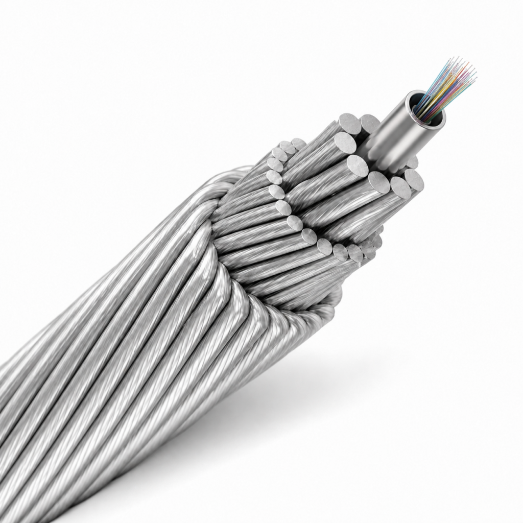
Choosing an OPGW fiber optic ground wire starts with the line rather than the fiber count: voltage class, ruling span, rated tensile strength and fault current decide the strand build before anything else. This guide works through a 24-core single-mode core OPGW cable with a metallic loose-tube optical unit and stranded aluminum-clad steel or aluminum-alloy wires, engineered to IEC 60794-4-10 and IEEE 1138, and shows which datasheet fields to check before a quotation is approved.
Design inputs
Sizing matrix: project input to build consequence
Six inputs drive an OPGW build. The matrix below shows what each one changes inside the cable, what to send with your enquiry, and the decision that has to be settled before two quotations can be compared fairly.
| Project input | What it changes in the cable | What to send | Buyer decision |
|---|---|---|---|
| Voltage levelLine class and earthing arrangement | The duty envelope the ground wire is designed against, and the standards package the quotation is checked against | Operating voltage and line class | Fix the line class before comparing prices; a design carried over from another voltage level is not comparable |
| Span lengthRuling span on the route | Tension and sag behaviour, and therefore the strand build and the tensile strength the cable must reach | Longest ruling span, plus any long-crossing cases | Decide whether the route is governed by a standard span or by one exceptional crossing |
| Rated tensile strengthRTS required by tower loading | Number and diameter of the stranded aluminum-clad steel or aluminum-alloy wires, and the outer diameter that follows | Required RTS | Derive RTS from tower loading, never from a catalogue number picked at random |
| Short-circuit currentFault current through the ground wire | The short-circuit capacity the finished cable must carry, which is coupled to the same strand build as RTS | Fault current and its clearing duration | Insist that current and duration are quoted together — one without the other cannot be checked |
| Fiber count and typeOptical capacity of the line | The number of fibers held in the metallic loose-tube optical unit | 24 cores as the standard; other counts on request; G652D or G657A | Reserve spare fibers now — re-entering a strung line later costs far more than extra fiber at build stage |
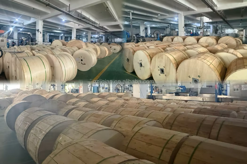
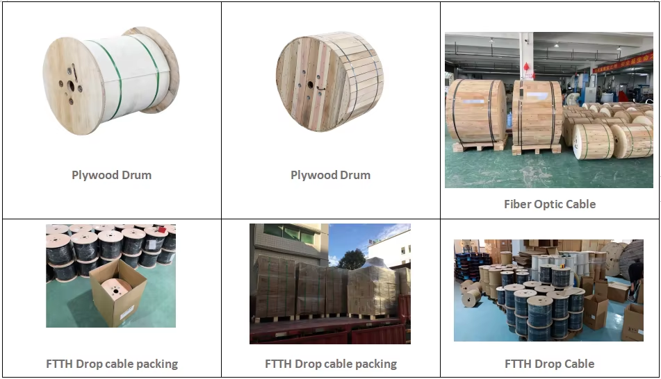
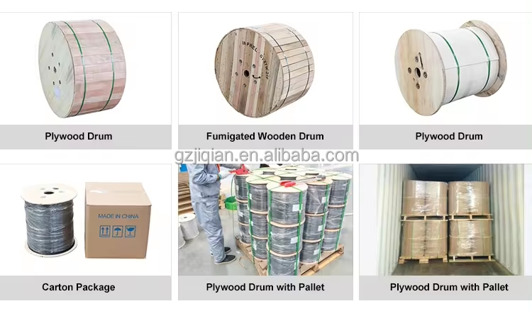
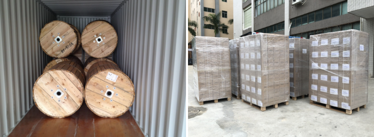
| Route environment and destinationIce, wind, coastal or industrial exposure | Sheath and UV expectations, plus the drum length and shipping plan the delivery has to fit | Loading conditions, route environment, delivery port or site | Agree drum lengths against your tensioner set-up and right-of-way access before the order is placed |
Start with the row that matches your binding constraint — usually RTS on a long span, or fault current on a heavily earthed line.
Send the electrical and mechanical inputs together. A fiber count on its own cannot be quoted as a design.
Compare returned quotations field by field against the datasheet checklist further down the page.
Construction
How the optical unit, the strands and the duty envelope are coupled
The 24 single-mode fibers sit inside a metallic loose-tube optical unit at the centre of the cable. The tube keeps the optical path mechanically stable, while the metallic element takes part in the fault-current path that an overhead ground wire has to provide.
Around that unit, aluminum-clad steel or aluminum-alloy wires are stranded. Their count and diameter set both the outer diameter and the rated tensile strength, so the strand lay is the real mechanical specification of the cable rather than packaging around it.
This is why a fiber count is not a specification. A 24-core and a 48-core can follow the same optical logic but cannot share a duty envelope: lift the strand build to raise RTS and the short-circuit behaviour moves with it. Diameter, RTS and short-circuit capacity are therefore quoted as project values rather than fixed catalogue numbers.
- Fiber count24 cores; other counts available
- Fiber typeITU-T G652D; G657A available
- Optical unitMetallic loose-tube
- Outer strandsAluminum-clad steel / aluminum alloy wires
- StandardsIEC 60794-4-10, IEEE 1138
- CustomizationDiameter, RTS, short-circuit capacity, drum length
Paper trail
Datasheet and standards checklist before you approve a quotation
Missing fields are the usual reason a delivered drum does not match the line design. Work through these items with the quotation in front of you.
Routine tests
Routine tests are the checks applied to the cable lengths actually shipped. Ask for the routine test record that matches your drum numbers, so the report you file corresponds to the cable on site rather than to a design study.
Type tests
Type tests qualify a design rather than a single production run. Ask for the type-test report covering the construction family you are buying, and confirm whether the tested construction is identical to the one offered — a different strand build is a different design.
Application
Match the application to the build
The same 24-core construction serves several jobs on a network, but each one shifts which input dominates the specification.
Ground wire and communication path in one
What it changes: fiber count and mechanical duty are fixed at the same design stage, so the optical unit and the strand build have to be chosen together.
Buyer decision: reserve spare fibers in the initial build; adding capacity to a strung line later is a re-stringing project, not an accessory.
Fitting an existing mechanical envelope
What it changes: the constraint is matching what is already on the towers — diameter and RTS drive the quotation more than optical ambition.
Buyer decision: measure the existing ground wire and the tension hardware before specifying, then state the envelope in the enquiry.
Protection and telemetry links
What it changes: short runs between structures and buildings, where fiber type and termination planning matter more than long-span tension.
Buyer decision: confirm G652D or G657A, and settle the termination and splice plan before the drum length is fixed.
Mixed routes across an existing network
What it changes: spans vary along the route, so drum lengths become a logistics variable as much as a cable variable.
Buyer decision: split the order into drum lengths that match access points and tensioner positions along the right-of-way.
Project build
Drum length, marking and project-specific builds
The construction is engineered to the project rather than picked from a fixed list. Fiber count, conductor combination and drum length are all open to project customization, and the cable structure can be set to the tower span, rated tensile strength, short-circuit current capacity and the environmental conditions on the route.
For utilities, EPC contractors and telecom infrastructure projects, that means the quotation should describe your line, not a generic reel. UV resistance and low attenuation are stated for the construction, so the outer sheath and the optical performance can be discussed in the same conversation as the mechanical values.
- Open to customizationDiameter, RTS, short-circuit capacity, drum length
- Optical optionsFiber count and G652D / G657A selection
- Supply modelFactory supply with project-specific design
- InstallationOverhead power transmission lines
Acceptance
Optical verification before the cable goes on the towers
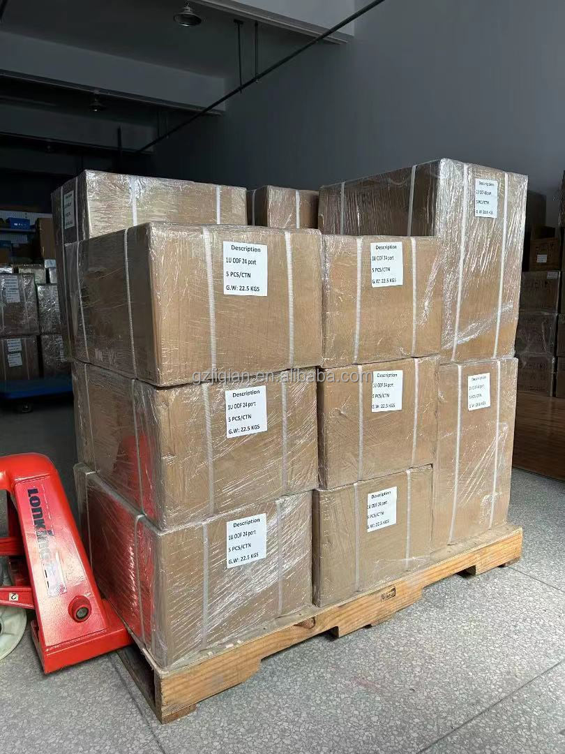
Low attenuation is a stated property of this construction, but the acceptance step belongs to the delivery, not to the brochure. Check the attenuation record against the drum you received, and confirm that drum numbers on the report match drum numbers on the labels.
Inspect the drum before signing: cable ends sealed, outer sheath free of handling damage, and the length as ordered. A drum stored badly or unloaded carelessly can pass every factory check and still fail at stringing, so keep the acceptance conversation with the delivery rather than with the design.
When something does not reconcile — a length that differs, a report that does not match, an optical reading outside the quoted figure — raise it before installation starts, while the cable is still on the drum.
Request a quote
Six inputs turn into an orderable OPGW build
A tailored design and quotation is prepared from the inputs below. Send all six together and the reply can be a configuration, not a question list.
Quotation responses are typically returned within 12 to 24 hours. For a direct technical discussion, call +86 153 6086 9138.
Frequently Asked Questions
what information is shown for this product?
review the product details, images, and specifications presented on the official product page.
where can i check the intended application?
use the application and use-case information published on the official product page.
which specifications should i confirm before ordering?
confirm the specifications and options listed for the exact product variant before placing an order.
where can i check available options?
check the official product page or ask the supplier about options shown for the selected product.
how can i request product information?
use the official contact or inquiry path provided on the site.
what should i include in an inquiry?
include the product page, intended use, required quantity, and any specifications you need the supplier to review.
