
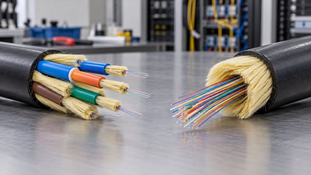
Introduction: Breakout and distribution fiber cables both serve indoor backbones, but independent subunit protection versus one shared jacket changes termination materials, field handling, and where each construction fits.
A junior technician opening a cut sheet for an indoor backbone run sees the two cable names side by side, and they look interchangeable: both are multi-fiber, both are indoor rated, both can move a dozen strands between a telecom room and a rack. The difference that decides the day sits inside the jacket. Breakout cable builds a protective layer around every fiber; distribution cable builds one around the group. That single choice drives which tools and materials show up on the cart, how the panel work goes, and how much room the cable needs in a tray or shaft. The construction logic comes first, then everything it changes in the field.
Why Subunit Protection Changes the Cable Design
A backbone cable does three jobs at once: it survives the pull, it lives in a tray or riser, and then it has to be split into fibers somebody can actually terminate. The third job is where breakout and distribution part ways. Protection can be wrapped around each fiber from the inside out, or it can be wrapped around the bundle and shared. Jacket organization, outer bulk, and the way the cable behaves once the jacket comes off all follow from that one decision.
1. Independent Subunits Give Each Fiber Its Own Protective Layer
In a breakout design, each fiber sits inside its own 900 μm tight-buffered subunit, a protective layer applied directly onto the glass. A 12-core indoor breakout cable such as the JIQIAN GJPFJV carries twelve of these subunits inside a single outer jacket, with aramid yarn for tensile reinforcement, an LSZH sheath, and no metallic components anywhere in the build. The practical result appears the moment the outer jacket is stripped: what is left is not bare fiber but twelve small finished cables, each one able to be bent, routed, labeled, and terminated on its own. Protection travels with the fiber right up to the connector body instead of stopping where the jacket stops.
2. Shared Jacket Designs Organize Fibers With Less Outer Bulk
Distribution cable works the other way around. Multiple fibers — typically 250 μm fibers or small bundles — are gathered inside one shared jacket, with strength members and binders holding the group together. Protection comes from the arrangement as a whole rather than from a layer on each strand. That packs fiber efficiently: for the same strand count, distribution construction usually ends up slimmer and lighter, which matters when trays, conduits, and riser shafts have limited fill. The cost shows up at the break-out point. A fiber that leaves a shared jacket arrives with no protective layer of its own, so something has to be added before it can reach a connector.
How Termination Materials and Field Work Differ in Practice
The 900 μm subunit is the reason breakout cable is associated with direct connectorization. Standard connector bodies and boots are sized for that buffer diameter, so a technician who strips the subunit back, cleans the fiber, cleaves it, and crimps or cures the connector is working with a finished, self-supporting element. The furcation tubing, breakout boots, and heat-shrink fan-out kits that normally bridge the gap between jacket and connector have less to do here, because the subunit already fills that role. That trims the small-parts pile at the panel, while stripping, cleaning, cleaving, and connector assembly still happen exactly as they always do. Distribution cable changes the material list. Once the shared jacket opens, the 250 μm fibers need a protected path to the connector, and that path is a fan-out kit: furcation tubing slid over each fiber, a breakout boot anchoring the tubing to the jacket, and often a splice into a pigtail inside a tray. Every one of those parts adds material cost and another place for handling to go wrong. In exchange, distribution construction is very efficient where the run ends at a splice tray and the fibers get spliced once, in bulk, and never touched individually again. In those spots a slim cable and a tidy tray beat a bundle of individual subunits. The balance shifts with the endpoint. Breakout earns its keep when the split happens at a patch panel where every fiber gets its own connector. Distribution earns its keep when the split is a single, high-count splice event. Neither construction removes the fiber work; one moves the labor into the jacket, the other moves it into the tray, and a technician who knows which is which plans the day accordingly.
Where Indoor Backbone Cabling Uses Each Construction
Breakout construction shows up in vertical riser shafts, equipment rooms, and data center rows where the cable lands at panels and each strand is connectorized on site or in a pre-terminated assembly. Twelve strands is a common shape for that job: enough fiber for a small distribution frame, an all-dielectric LSZH build that suits indoor trays and shafts, and subunits that can be split off one at a time as racks fill up. Riser work also rewards the extra protection, because a subunit tolerates the handling that happens when a bundle is dressed into a shaft and tied off. Distribution construction fits long backbone segments with higher strand counts, where most fibers pass through a splice tray and never get handled individually, and where outer diameter and tray fill are the binding constraint. Both constructions come in the same all-dielectric LSZH jacket family, so the visible cable often looks similar; what changes is how much jacket is being bought per fiber. The deciding question is where the split happens and how often it repeats. Split at both ends, repeatedly, in crowded racks: breakout. Split once, in a tray, with a high count: distribution. Where a project sits near that line, the numbers settle it — outer diameter, weight, and minimum bend radius for the specific construction and strand count. Those come from the datasheet, and a fiber optic cable manufacturer that publishes subunit diameter and jacket compound alongside strand count gives a technician enough to compare like with like instead of guessing from the name on the drum.
Conclusion
Breakout and distribution cable are two answers to the same question: where should the protection live? Breakout puts it on every fiber, so the cable arrives at the panel ready to split into individual strands that each survive handling. Distribution puts it around the group, so the same fiber count fits into a slimmer jacket and works best where the split happens once, in a tray, and stays put. A junior technician who can name that difference, and then check outer diameter and subunit details on the spec sheet, can look at any indoor backbone run and say which construction actually suits it. Anyone comparing indoor fiber optic cable listings can apply the same test before the first cable is pulled.
FAQ
Q: What is the main structural difference between breakout and distribution fiber cable?
A: Breakout cable places each fiber inside its own 900 μm tight-buffered subunit, so every strand carries a protective layer that travels with it. Distribution cable groups multiple fibers inside one shared jacket, with strength members and binders protecting the bundle as a unit. One protects fiber by fiber, the other protects the group.
Q: Why does a breakout cable often reduce the need for separate fan-out kits?
A: A fan-out kit exists to give a bare 250 μm fiber a protected path from the jacket to the connector. In breakout cable that path already exists, because the 900 μm subunit is the right size for standard connector bodies and boots. The technician strips the subunit and terminates directly, so furcation tubing and breakout boots are usually unnecessary.
Q: When is a distribution cable still a reasonable choice for indoor backbone cabling?
A: Distribution cable makes sense on long backbone segments with high strand counts, where most fibers pass through a splice tray, get spliced once, and are never handled individually again. Its slimmer jacket also helps where tray fill, conduit space, or riser capacity is tight. In those runs the compact build outweighs the extra fan-out work at the ends.
Sources / References
IEC 60794-2-30:2008 | IEC
The FOA Reference For Fiber Optics – Fiber Optic Cables
The FOA Reference For Fiber Optics – Optical Fiber
Related Examples
GJPFJV 12-Core LSZH Indoor Breakout Fiber Optic Cable
