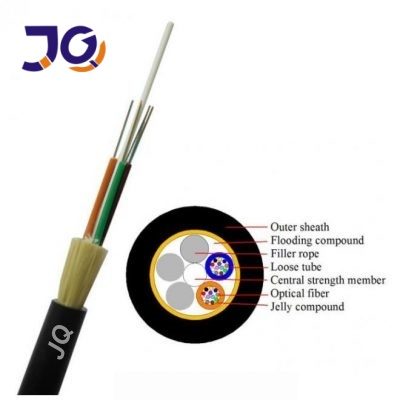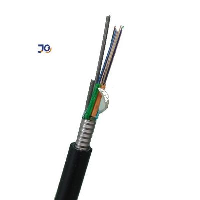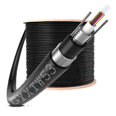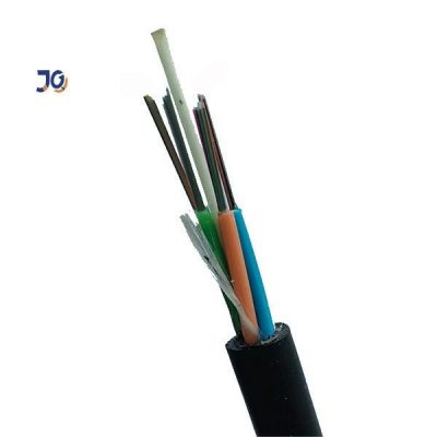
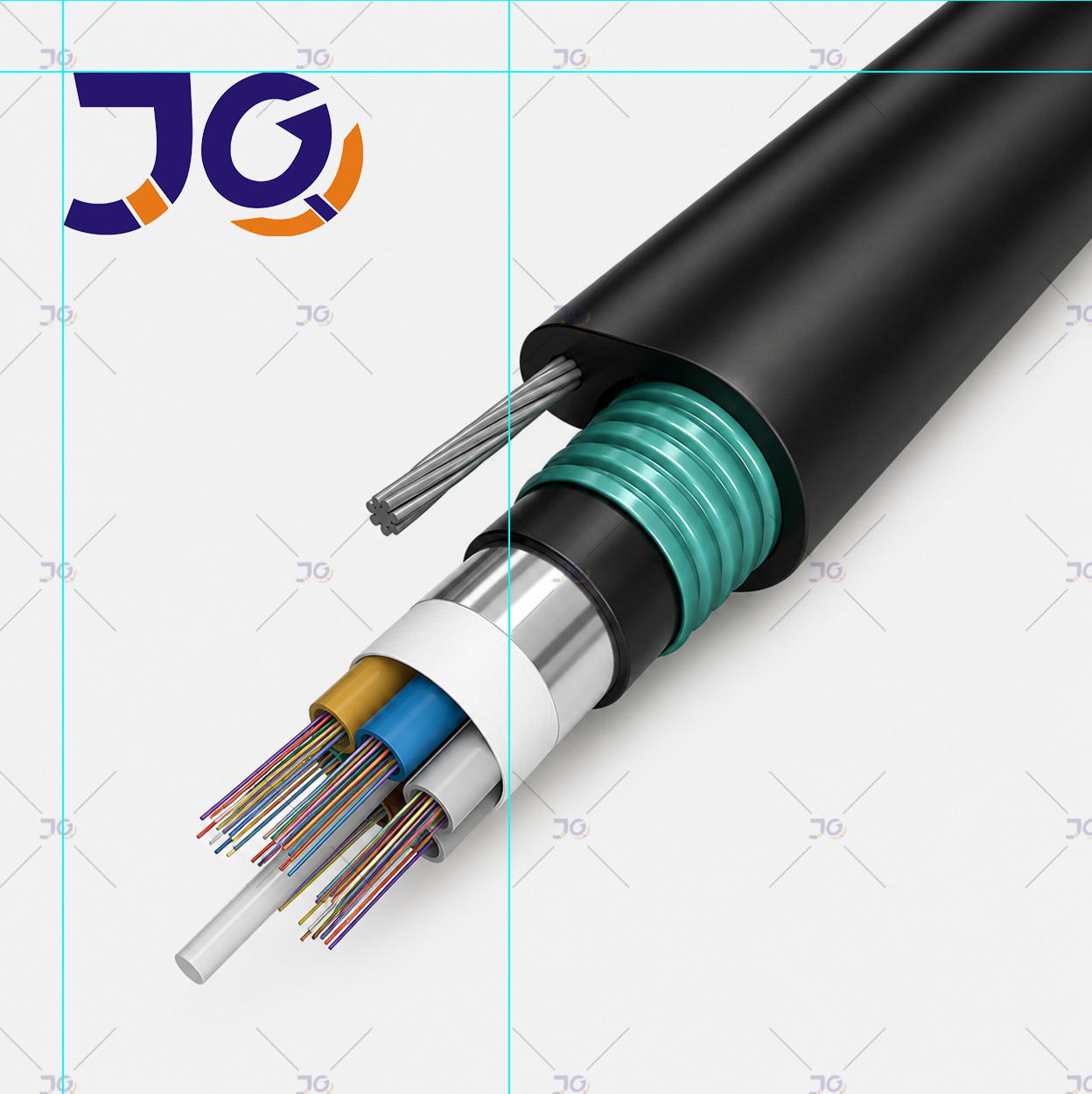
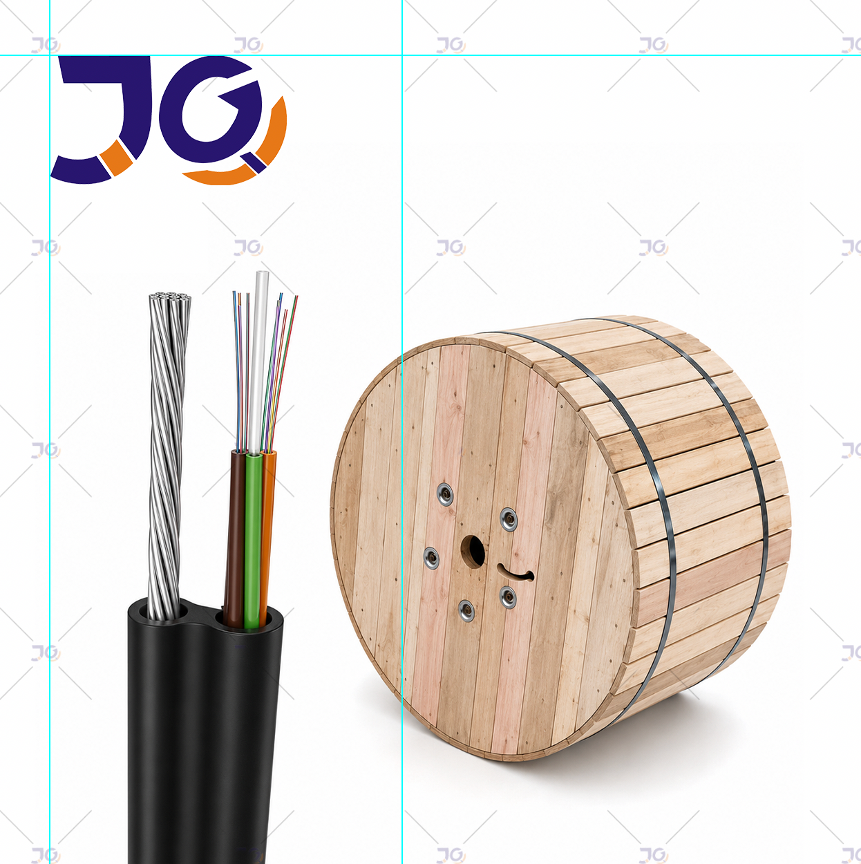
Structure Design:
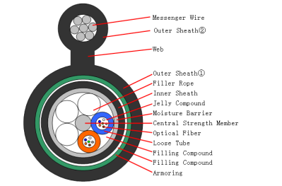
Main Feature:
1. Accurate optical fiber excess length ensures good mechanical and temperature performance.,
2. High strength loose tube that is hydrolysis resistant and special tube filling compound and flexibility.
3. Figure 8 self supporting type structure possesses high tensile strength and is convenient for aerial installation and its installation cost is cheap.
4. The service life of the products willbe more 30 years.
5. Light, flexible, easy for the laying and it is used for FTTH solution.
Technical Parameters:
|
No. of cable |
6 |
12 |
24 |
48 |
96 |
||
|
Fiber Model |
G.652D |
||||||
|
Design (StrengthMember+Tube&Filler) |
1+5 |
1+8 |
|||||
|
Central Strength Member |
Material |
Steel Wire |
|||||
|
|
Diameter(±0.5)mm |
1.8 |
|||||
|
Additional Sheath |
Material |
PE |
|||||
|
|
Diameter(±0.05)mm |
— |
3.2 |
||||
|
Loose Tube |
Material |
PBT |
|||||
|
|
Diameter(±0.06)mm |
1.65 |
1.9 |
||||
|
|
Thickness(±0.03)mm |
0.25 |
0.30 |
||||
|
|
The Max.Core NO./Tube |
6 |
12 |
||||
|
Filler Rope |
Material |
PE |
|||||
|
|
Diameter(±0.06)mm |
1.65 |
1.9 |
— |
|||
|
|
NO. |
4 |
3 |
1 |
1 |
— |
|
|
Moisture Barrier |
Material |
Polymer Coated Aluminum Tape |
|||||
|
Thickness(±0.03)mm |
0.20 |
||||||
|
Inner Sheath |
Material |
PE |
|||||
|
Thickness(±0.1)mm |
0.8 |
||||||
|
Armoring |
Material |
Polymer Coated Steel Tape |
|||||
|
|
Thickness(±0.02)mm |
0.22 |
|||||
|
Water Bloaking Layer |
Material |
Filling Compound |
|||||
|
Messenger Wire |
Material |
Galvanized steel strand |
|||||
|
|
Size |
R7×1.0 |
|||||
|
WEB |
Material |
PE |
|||||
|
|
Size |
2.5×3.0 |
|||||
|
Outer Sheath① |
Material |
MDPE |
|||||
|
|
Thickness(±0.2)mm |
1.5 |
|||||
|
Outer Sheath② |
Material |
MDPE |
|||||
|
|
Thickness(±0.2)mm |
1.7 |
|||||
|
Cable Diametermm(±0.5)mm |
11.7×20.2 |
12.2×20.7 |
14.0×23.5 |
||||
|
Cable Wetght(±10)kg/km |
210 |
220 |
275 |
||||
|
Attenuation |
1310nm |
0.35dB/ km |
|||||
|
|
1550nm |
0.21dB/ km |
|||||
|
Min. bending radius |
Without Tension |
12.5×Cable-φ |
|||||
|
|
Under Maximum Tension |
25.0×Cable-φ |
|||||
|
Temperature range (℃) |
Installation |
-20~+60 |
|||||
|
|
Transport&Storage |
-40~+70 |
|||||
|
|
Operation |
-40~+70 |
|||||
Fibre Colours:

Loose Tube Colours:

The properties of single mode optical fiber (ITU-T Rec. G.652.D)
|
G.652D Single-mode fiber characteristics |
|||
|
Characteristic |
Condition |
Data |
Unit |
| Optical properties | |||
| Attenuation | 1310nm1383nm1550nm1625nm | ≤0.35≤0.34≤0.21≤0.24 | dB/kmdB/kmdB/kmdB/km |
| Relative wavelength attenuation @1310nm@1550nm | 1285~1330nm1525~1575nm | ≤0.03≤0.02 | dB/kmdB/km |
| Dispersion in the wavelength range of | 1550nm | ≤18 | ps/(nm.km) |
| Zero dispersion wavelength | 1312±10 | nm | |
| A zero-dispersion slopezero-dispersion slope typical value | ≤0.0920.086 | ps/(nm2.km)ps/(nm2.km) | |
| Cable cut-off wavelength λcc | ≤1260 | nm | |
| Mode field diameter MFD | 1310nm1550nm | 9.2±0.410.4±0.5 | μmμm |
| Effective group refractive index | 1310nm1550nm | 1.4661.467 | |
| Attenuation discontinuities | 1310nm1550nm | ≤0.05≤0.05 | dBdB |
| Geometric characteristics | |||
| Core diameter | 124.8±0.7 | μm | |
| Cladding roundness | ≤0.70 | % | |
| Coating diameter | 245±5 | μm | |
| Coating / package concentricity error | ≤12.0 | μm | |
| Coating no roundness | ≤6.0 | % | |
| Core / package concentricity error | ≤0.5 | μm | |
| The warpage (radius) | ≥4 | m | |
| Environmental characteristics(1310nm、1550nm、1625nm) | |||
| Temperature additional attenuation | -60℃ ~+85℃ | ≤0.05 | dB/km |
| Flooding additional attenuation | 23℃,30 days | ≤0.05 | dB/km |
| Hot and humid additional attenuation | 85℃ and 85% Relative humidity, 30 days | ≤0.05 | dB/km |
| Dry heat aging | 85℃ | ≤0.05 | dB/km |
| Mechanical properties | |||
| Screening tension | ≥9.0 | N | |
| The macro bend Additional attenuation1Circle Ф32mm100Circle Ф50mm100Circle Ф60mm | 1550nm1310nm和1550nm1625nm | ≤0.05≤0.05≤0.05 | dBdBdB |
| Coating peeling force | Typical average | 1.5≥1.3 ≤8.9 | NN |
| Dynamic fatigue parameters | ≥20 | ||
Application:
|
NO. |
Item |
Requirement |
|
|
1 |
Allowable Tensile Strength |
Short Term |
5000 N |
|
|
|
Long Term |
2000 N |
|
2 |
Allowable Crush Resistance |
Short Term |
3000 (N/100mm) |
|
|
|
Long Term |
1000 (N/100mm) |
Main mechanical & environmental performance test
|
Item |
Test Method |
Acceptance Condition |
| Tensile StrengthIEC 794-1-2-E1 | – Load: Short term tension– Length of cable: about 50m | – Fiber strain £ 0.33%– Loss change £ 0.1 dB @1550 nm– No fiber break and no sheath damage. |
| Crush TestIEC 60794-1-2-E3 | – Load: Short term crush– Load time: 1min | – Loss change £ 0.05dB@1550nm– No fiber break and no sheath damage. |
| Impact TestIEC 60794-1-2-E4 | – Points of impact: 3– Times of per point: 1– Impact energy: 5J | – Loss change £ 0.1dB@1550nm– No fiber break and no sheath damage. |
| Temperature Cycling TestYD/T901-2001-4.4.4.1 | – Temperature step:+20oC→-40oC→+70oC →+20oC– Time per each step: 12 hrs– Number of cycle: 2 | – Loss change £ 0.05 dB/km@1550 nm– No fiber break and no sheath damage. |
Sheath marking:
The color of marking is white, but if the remarking is necessary, the White color marking shall be printed newly on a different position.
An occasional unclear of length marking is permitted if both of the neighboring markings are clear.
The both cable ends are sealed with heat shrinkable end caps to prevent water ingress.
Specification of Optical Fiber:
| (Item) | Unit | Specification | Specification | Specification | Specification | |
| G. 657A1 | G. 657A2 | G. 652D | G. 655 | |||
| Mode field diameter | 1310nm | mm | 8.6-9.5 ± 0.4 | 8.6-9.5 ± 0.4 | 9.2 ± 0.4 | 9.6± 0.4μm |
| Cladding diameter | mm | 125.0 ± 0.7 | 125.0 ± 0.7 | 125.0 ± 1 | 125 ±0.7μm | |
| Cladding non-circularity | % | £1.0 | £1.0 | £1.0 | £1.0 | |
| Core/cladding concentricity error | mm | £0.5 | £0.5 | £0.5 | £0.5 | |
| Coating diameter | mm | 245 ± 5 | 245 ± 5 | 242 ± 7 | 242 ± 7 | |
| Coating/cladding concentricity error | mm | £12 | £12 | £12 | £12 | |
| Cable cut-off wavelength | nm | £ 1260 | £ 1260 | £ 1260 | £ 1260 | |
| Attenuation Coefficient | 1310nm | dB/km | £0.36 | £0.36 | £0.35 | £0.35 |
| 1550nm | dB/km | £0.22 | £0.22 | £0.22 | £0.22 | |
| 1 turn on 10±0.5mm Dia. Mandrel | 1550nm | dB/km | £0.75 | £0.5 | – | – |
| 1 turn on 10±0.5mm Dia. Mandrel | 1625nm | dB/km | £1.5 | £1.0 | – | – |
| Proof stress level | kpsi | ≥100 | ≥100 | ≥100 | ≥100 | |
| (Item) | Unit | Specification | Specification | Specification | Specification | |
| OM1 | OM2 | OM3 | OM4 | |||
| Mode field diameter | 1310nm | mm | 62.5±2.5 | 50±2.5 | 50±2.5 | 50±2.5 |
| 1550nm | mm | 125.0 ± 1.0 | 125.0 ± 1.0 | 125.0 ± 1.0 | 125.0 ± 1.0 | |
| Cladding diameter | mm | £1.0 | £1.0 | £1.0 | £1.0 | |
| Cladding non-circularity | % | £1.5 | £1.5 | £1.5 | £1.5 | |
| Core/cladding concentricity error | mm | 245 ± 10 | 245 ± 10 | 245 ± 10 | 245 ± 10 | |
| Coating diameter | mm | £12 | £12 | £12 | £12 | |
| Coating/cladding concentricity error | mm | ≥ 160 | ≥ 500 | ≥ 1500 | ≥ 3500 | |
| Cable cut-off wavelength | nm | ≥ 500 | ≥ 500 | ≥ 500 | ≥ 500 | |
| Attenuation Coefficient | 1310nm | dB/km | £3.5 | £3.5 | £3.5 | £3.5 |
| 1550nm | dB/km | £1.5 | £1.5 | £1.5 | £1.5 | |
| Proof stress level | kpsi | ≥100 | ≥100 | ≥100 | ≥100 | |
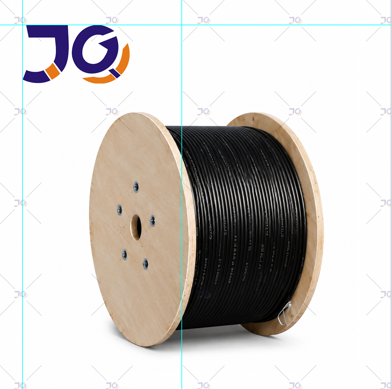
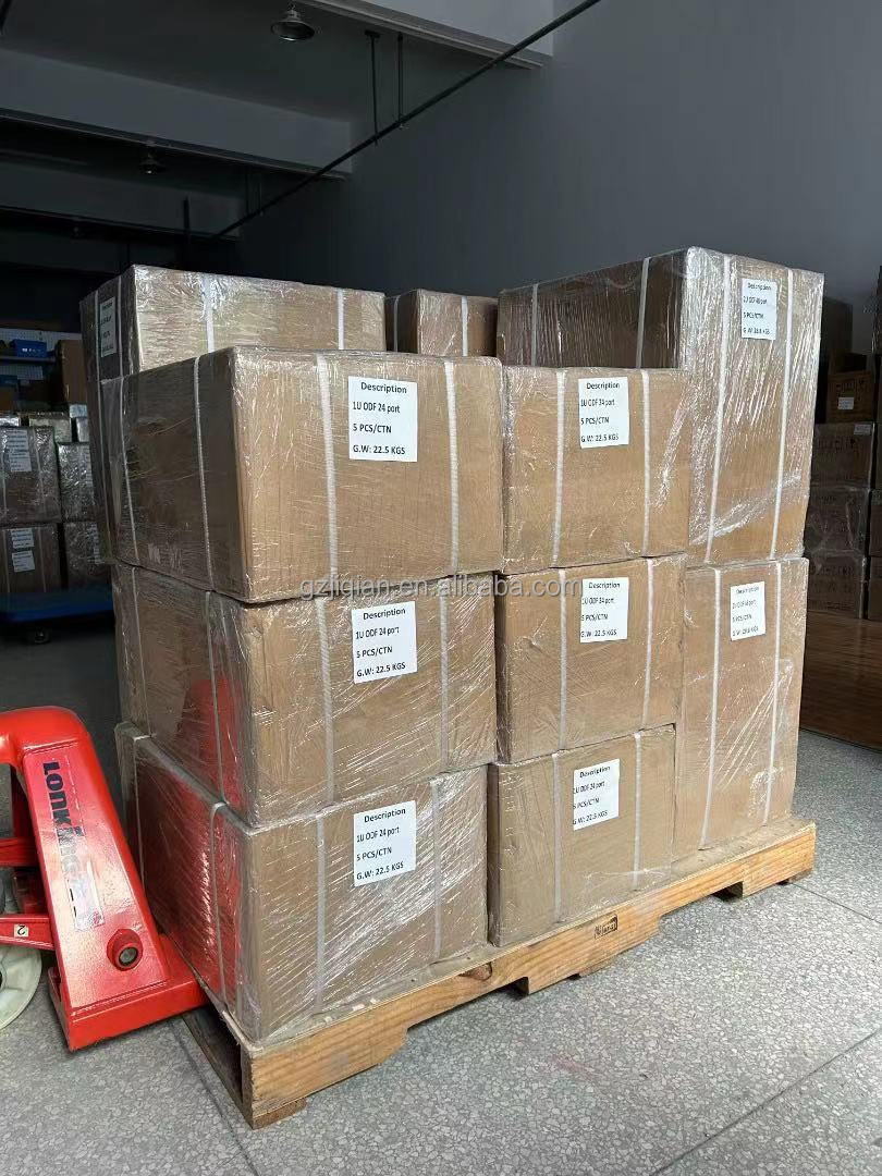
Our Packing and Delivery Process
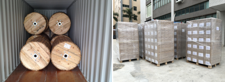
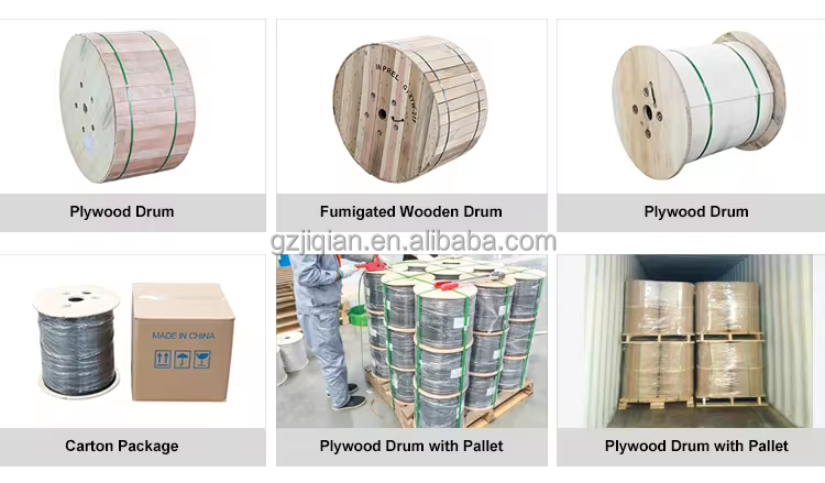
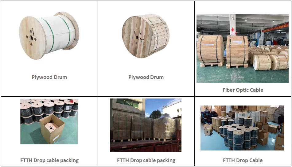
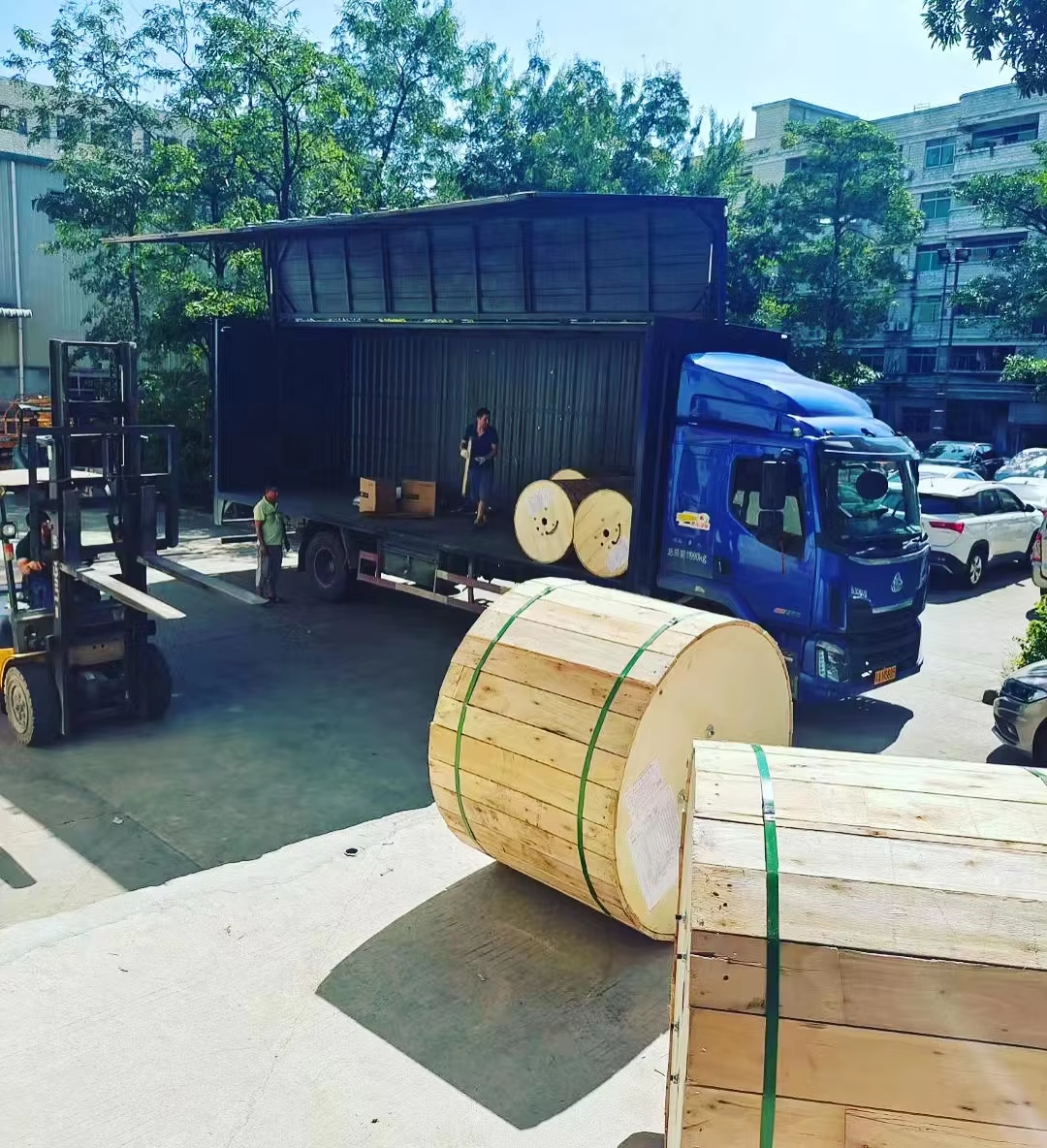
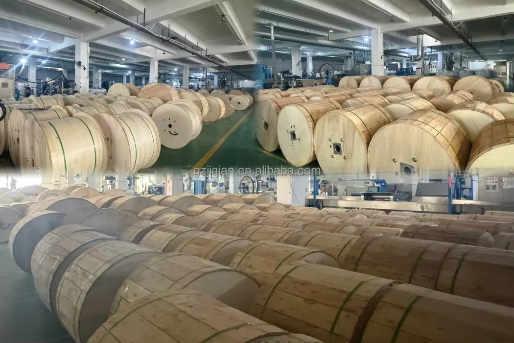
Our Packing and Delivery Process